New terminal with special connections, 1.5 mm²
VPC.2/S is a 1.5 mm² screw terminal block for female connectors pitch 5.08 mm with aligned outputs.
€197,50 + VAT
Temporarily not available for online purchase. Contact our sales department.
Temporarily not available for online purchase. Contact our sales department.
| Series | MCM |
|---|---|
| Code | MC201G |
| Type | MCM.1/G |
| HS code | 85369010 |
| Colour | Yellow |
| TECHNICAL FEATURES | |
| Function/Type | Sectioning and measurement |
| Rated cross-section | 6 mm² |
| Rated cross-section | |
| Connecting capacity | |
| Flexible wire | 0.5-6 mm² |
| Rigid wire | 0.5-6 mm² |
| Electrical characteristics according to IEC EN standard | |
| Maximum voltage AC/DC | 500 V |
| Maximum current (rated cross-section) | 57 A |
| Protection degree | IP20 |
| Rated impulse withstand voltage / pollution degree | 6 kV / 3 |
| Insulation stripping length | ‒ |
| Tightening torque value (nom. / max.) | 1.2 Nm |
| Dimension | 85x95x48 mm (AxBxH) |
| Plastic material | Kelon UL94V-0 |
| ACCESSORIES | |
| Protection cover | – |
| APPROVALS AND MARKINGS |
For further information see PDF catalog

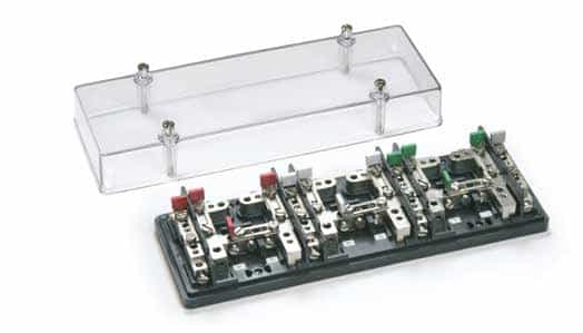
Cabur control terminal boards have been developed in order to enable electric power suppliers and users to easily check measuring instruments, without interrupting the current carrying circuits during the verification itself or during the replacement of the instruments.
Each terminal board is composed by an insulating body, carrying the copper zinc alloy terminals to which the ammeter, voltmeter circuits and the devices for disconnect and short circuit operations are connected. Each terminal board is supplied with a transparent cover (of cellulose acetate), provided with appropriate captive screws for the sealing of the assembly.
In two-phase and three-phase terminal boards, the insulating base is built from Kelon (an abbreviation of Keramic + Nylon): this is a nylon 6 based, self-extinguishing UL94V-0 polymer with the addition of special ceramic spheres and subsequent thermal stability. The inclusion of the microspheres and the thermal procedure make the item extremely hardwearing (rigid, but also able to withstand impacts and wear and tear)
The current phases are marked in different colours, to be defined when ordering.
The use of MCM series control terminal boards allows:
In normal service, voltmeter leads are connected to the R-S-T terminals, whilst the ammeter leads, are to be inserted in the terminals identified R1‑R2, S1-S2,
T1‑T2. The instruments are connected to terminals 1 and 2. The vertical slide‑link cross connections are closed, the horizontal slide-link
cross connections are open.
When inserting control instruments, the following instructions are to be followed:
– by means of normal plugs, the voltmeter leads must be shunted from the
test instrument on to the voltage sockets of the disconnect slide-link or to the
insertion blocks of the fuse-holders;
– the ammeter leads of the test instruments must be inserted in sockets 1 ad
R1 or 2 ad R2; same procedure is to be followed for the other phases;
– therefore, the corresponding vertical slide-link must be disconnected.
If there is a need to replace a measuring instrument, it is necessary to
previously close the horizontal slide-links, disconnect the vertical slide-links and
open the slide-link.
Feeding conductors (incoming and outcoming) are inserted from the rear of the
terminal board, with conductors passing through slots on the insulating base of
the terminal board

VPC.2/S is a 1.5 mm² screw terminal block for female connectors pitch 5.08 mm with aligned outputs.

The new “Easy Bridge Plus” multi-pole cross connections for CBC.6 terminal blocks are available in red or blue colours for instant visibility. If needed, the upper surface can be marked with a permanent marker to highlight the presence of the pole and of the electrical connection with the underlying terminal block in pole skipping cross connection configurations.

The new products extend the range of Cabur’s Easy Fast Connection (EFC) series, spring clamp terminal blocks with push-in technology.


Copyright © Cabur srl Sede legale Località isola Grande, 45 – 17041 Altare (SV) – Italia – Tel. 019-589991 – Fax 019-58999233 – E-mail: info@cabur.it
Cap. Sociale: €2.000.000 Int. versato – Reg. Soc. Trib. Savona N° 4635 – C.C.I.A.A. N° 27269- Export N° SV 000532 – Iscrizione al Registro AEE n. IT18050000010376 – P.IVA e Cod. Fisc.: 00100760099
DISCLAIMER Cabur Srl may change and update any document available online without any obligation to inform users. Only cabur.it and cabur.eu domains are registered and maintained by Cabur srl. Cabur has no responsibility for contents published on sites under the same name, with different extensions from .it and .eu
To provide the best experiences, we and our partners use technologies like cookies to store and/or access device information. Consenting to these technologies will allow us and our partners to process personal data such as browsing behavior or unique IDs on this site and show (non-) personalized ads. Not consenting or withdrawing consent, may adversely affect certain features and functions.
Click below to consent to the above or make granular choices. Your choices will be applied to this site only. You can change your settings at any time, including withdrawing your consent, by using the toggles on the Cookie Policy, or by clicking on the manage consent button at the bottom of the screen.
for technical support
+39 019 58999.219 customercare@cabur.it
for commercial support
+39 019 58999.609 vendite@cabur.it
from monday to friday 8:30-12:30 13:00-17:00